Using the Comparison Viewer
🕐 Read time: 4 min
Written By Clark Yuan
Last updated About 2 months ago
Overview
The Comparison Viewer lets you view two raster layers side-by-side in a split-screen layout directly inside the 2D Viewer. It is built for change detection, progress tracking, inspection workflows or any situation where you need to compare two states of the same site or two different data types at a glance.
Common use cases include:
Before you start
The Comparison Viewer is a 2D-only feature. It is not available in the 3D Viewer (yet).
You need at least one raster layer uploaded to your Project. Two rasters give you the most useful comparison, but you can also compare a single raster against vector or annotation overlays on the other side.
Raster layers must already be uploaded before opening the Comparison Viewer; you cannot upload mid-session.
How to open the Comparison Viewer
Open your Project and enter the 2D Viewer using the View Toggle in the top left of the Viewer.
Click the Compare button in the toolbar at the top center of the Viewer, in the same row as the Point, Distance, and Area tools.
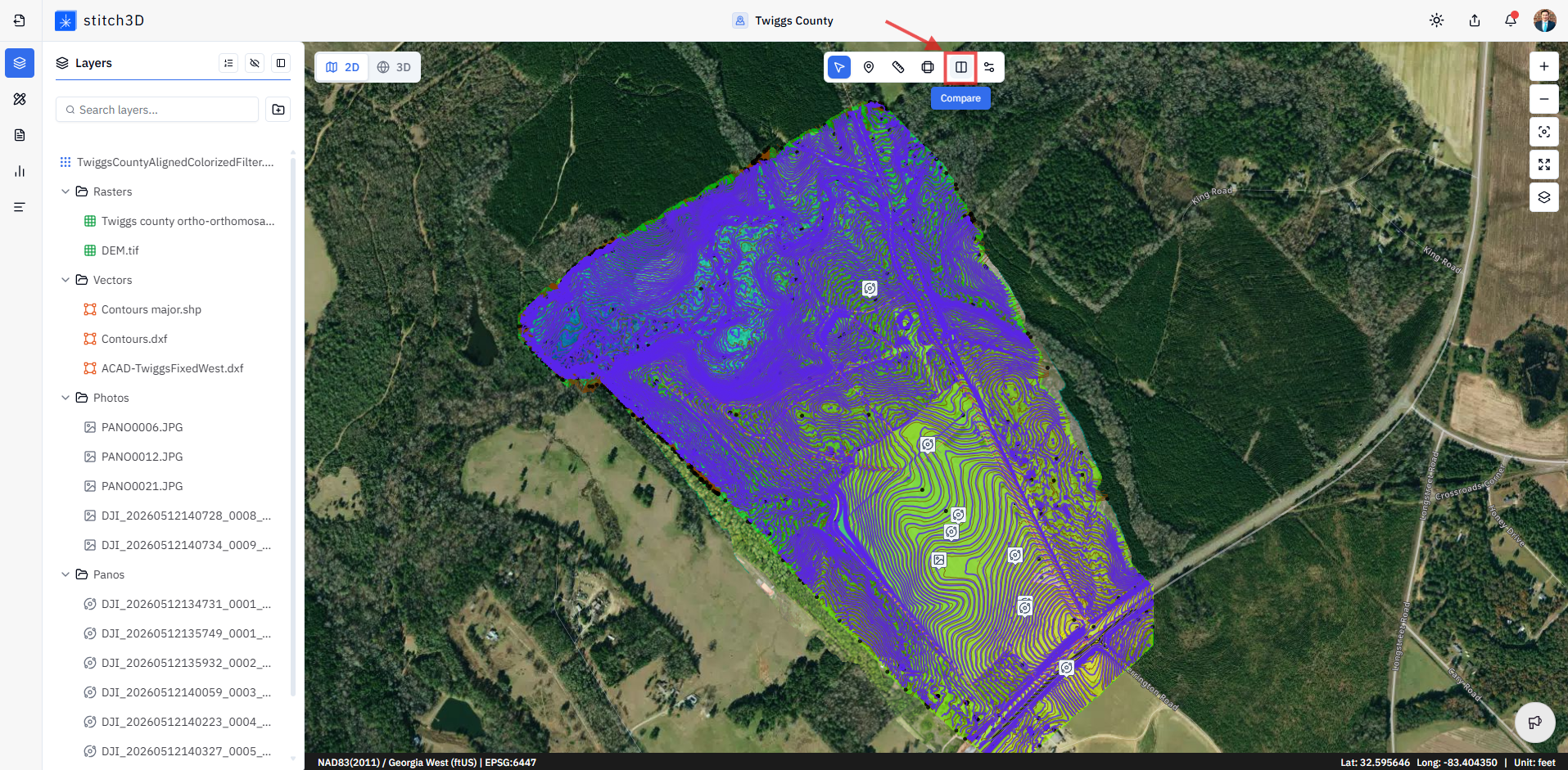
✅ The Comparison Viewer opens as a split-screen layout with two independent view boxes — left and right.
Selecting your base layers
Each side of the split screen has its own base layer selector.
In each view box, click the Base layer dropdown to choose which raster to display.
Your available options are the raster files already uploaded to the Project — orthomosaics, DEMs, and any other GeoTIFF files.
Select a different raster for each side to set up your comparison.
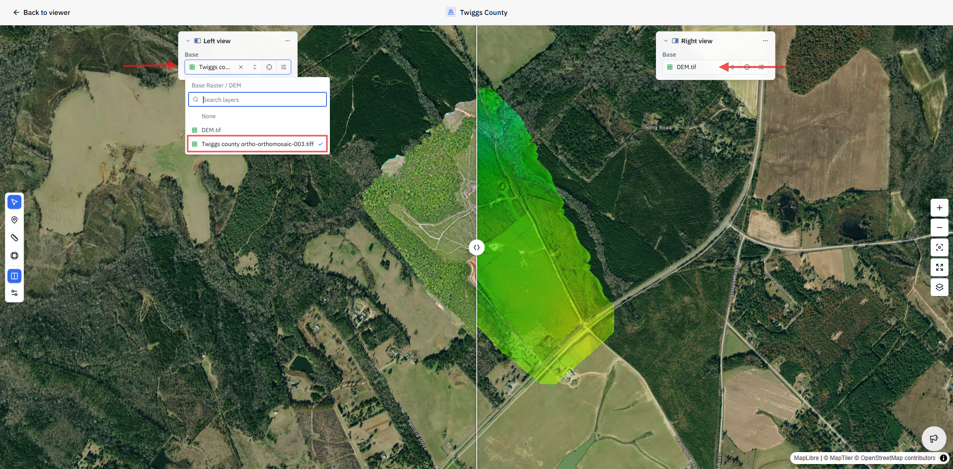
💡 Tip: To compare the same site across two capture dates, upload both orthomosaics to the Project before opening the Comparison Viewer, then assign one to each side.
Adjusting layer display settings
Each view box has independent display settings so you can fine-tune how each layer looks without affecting the other side.
Click the Edit layer button next to the zoom button, which sits next to the base layer file name at the top of each view box.
Adjust the display settings for that layer such as opacity, brightness, contrast, saturation for orthomosaics; hillshade, slope, and vertical exaggeration for DEMs.
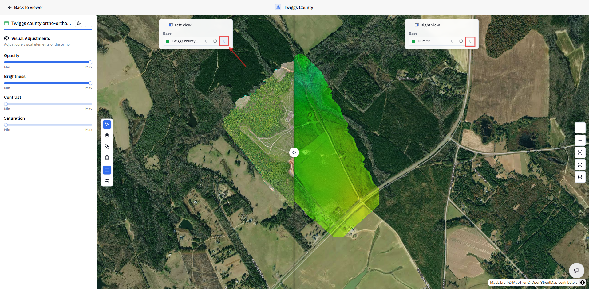
ℹ️ Note: Display settings in the Comparison Viewer are independent for each side. Adjusting one view does not affect the other.
Adding overlay layers
You can layer additional datasets on top of each base layer — vectors, annotations, GCPs, and media — to enrich each side of the comparison independently.
Click the ⋯ Layer options button in the top right corner of the view box you want to add a layer to.
Select the dataset you want to add: Vectors, Annotations, GCPs, or Photos.
Choose the specific file from your available Project layers.
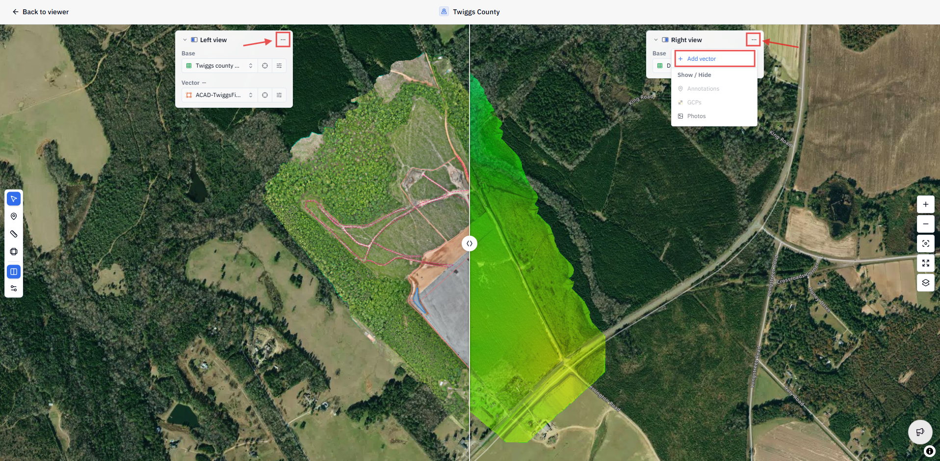
Overlay rules:
You can only add one vector layer per side.
Each side can have a different vector layer, enabling direct comparison of two different datasets. For example, a DXF engineering drawing on the left versus a Shapefile terrain contour on the right.
GCP and photo overlays can be added to either or both sides independently.
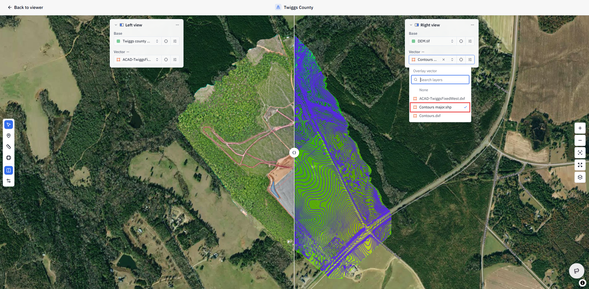
💡 Tip: Comparing vector overlays works well even with a single raster base layer. Load the same orthomosaic on both sides, then add different vector datasets to each side to see how different data layers relate to the same imagery.
Making annotations in the Comparison Viewer
You can place annotations and take measurements directly inside the Comparison Viewer using the same annotation toolbar available in the standard 2D Viewer.
Any annotation or measurement made in the Comparison Viewer is automatically saved to the Project. When you exit the Comparison Viewer and return to the standard Viewer, all annotations will be visible in the Annotations Panel.

ℹ️ Note: Measurements cannot be made across the dividing line in the Comparison Viewer.
💡 Tip: The Comparison Viewer is particularly useful for inspection workflows. Note differences, flag issues, and place point annotations as you step through a comparison. Everything saves automatically so your inspection record is ready when you exit.
Exiting the Comparison Viewer
Click the Compare button again in the toolbar to exit the Comparison Viewer and return to the standard 2D Viewer. You can also click the Back to viewer button in the top left corner of the viewer. All annotations made during the session are preserved.
Related articles
Was this helpful?
Still need help? Ask the team